Fin-Tube Heat Exchangers
Overview
In ACHP, all of the heat exchangers that exchange heat with an air stream are of the fin-tube type. In practice, other types of heat exchangers (shell-tube, microchannel, etc.) are also possible, but they are not included in ACHP as of the development of this documentation.
Mathematical Description
(Source code, png, hires.png, pdf)

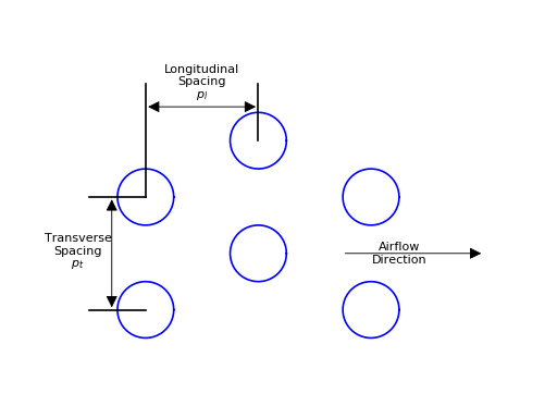
There is some disagreement in literature as to the best way to describe the tube layouts. The nomenclature used here is that there are a number of banks of tubes, where the banks are the vertical columns of tubes when viewed end-on with the air flow passing from left to right. The above heat exchanger has a total of 6 banks of tubes, with 4 tubes per bank; there are 4 refrigerant circuits.
There are then a certain number of tubes per bank which form the core of the heat exchanger (not considering the circuiting). The following figure defines the terms which describe the heat exchanger core, including the longitudinal spacing (also sometimes called bank-to-bank spacing),
(Source code, png, hires.png, pdf)
The empirical correlations for air-side heat transfer and pressure drop of fin-tube heat exchangers can be found in section Air-Side Correlations and Other Calculations, and the fluid-side correlations can be found in Fluid Correlations and Other Calculations.
In order to use the heat exchanger in ACHP, complexities of circuiting are neglected. In practice, it is uncommon for the number of tubes per bank to be divisible by the number of circuits. As a result, some circuits can be longer than others. For the purposes of ACHP, average circuit lengths are employed. The average circuit length is given by
This average circuit length is primarily required for the calculation of the fluid-side pressure drop. Other parameters that are required are the total refrigerant-side volume \(V_{r,total}\), which can be given by
where \(\pi D_i^2/4\) is the internal cross-sectional area of the tube. The refrigerant side surface area is given by
Air-Side Correlations and Other Calculations
(Source code, png, hires.png, pdf)

Geometric Parameters
Fins per meter [1/m]
Fin pitch (distance between centerlines of fins)
Spacing between fins
Height of heat exchanger [m], assuming that fin extends 1/2 \(P_t\) above/below last tube in bundle
\(A_{duct}\) is the face area [m2] equivalent to the duct cross-section
Number of fins in the tube sheet [-]
Secant of theta is the area enhancement factor [-]. It captures the increase in area due to the waviness of the fins
Duct cross-sectional area that is not fin or tube [m2]
Total outer area of the tubes [m2]
Wetted Area of a single fin [m2], assuming that fin extends 1/2 \(P_t\) in front/after last tube in bundle
Total wetted area of the fins [m2]
Total air-side area including tube and fins [m2]
Heat Transfer and Pressure Drop Parameters
Evaluate the mass flow rate based on inlet conditions
Specific heat, thermal conductivity and viscosity based on humid air property correlations.
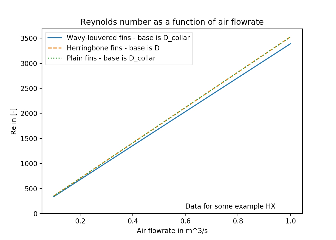
Reynolds number based on the tube diameter:
Empirical Overall Correlations
Wavy-Louvered fins from Wang,Tsai,Lu [3]:
Colburn j-Factor:
(20)¶\[j = 16.06 \mathrm{Re}_D^{-1.02 (p_f / D) - 0.256} \left(\frac{A_{a,total}}{A_{tube}}\right)^{-0.601} N_{bank}^{-0.069}\left(\frac{p_f}{D}\right)^{0.84}\]Air-side mean heat transfer coefficient:
(21)¶\[\alpha_a = \frac{j \rho_{ha} u_{max} c_{p,a}}{\mathrm{Pr}^{2/3}}\]Air-side pressure drop friction factor:
(22)¶\[ \begin{align}\begin{aligned}f_{a,total}=0.264(0.105+0.708\exp(-\mathrm{Re}_D/225.0))\mathrm{Re}_D^{-0.637}\left(\frac{A_{a,total}}{A_{tube}}\right)^{0.263}\left(\frac{p_f}{D}\right)^{-0.317} (\mathrm{Re}_D<1000)\\f_{a,total}=0.768(0.0494+0.142\exp(-\mathrm{Re}_D/1180.0))\left(\frac{A_{a,total}}{A_{tube}}\right)^{0.0195}\left(\frac{p_f}{D}\right)^{-0.121} (\mathrm{Re}_D\geq1000)\end{aligned}\end{align} \]
The air mass flux through the heat exchanger can be defined by
which yields the air-side pressure drop (neglecting entrance and exit pressure drops) of
Surface Efficiency
Thermal gradients in the fins result in a finned surface that does not perform as efficiently as if the entire finned surface was at the fluid temperature passing through the tubes. Correlation (or explicit solution where possible) is required to be used to determine the temperature profile in the fins, and from that, the finned surface efficiency.
Circular fins
Schmidt [4] developed a correction term for circular fins to calculate fin efficiency. Using the circular fin correlation of Schmidt yields the solution for the finned surface efficiency of
where \(r\) is the outer diameter of the tube, and \(r_f\) is the outer radius of the circular fin. The parameter \(m\) is given by
Staggered tubes
For the staggered tube bank configurations (like that in ACHP), hexagonal cells with adiabatic boundaries are formed around each tube, and for each cell the fin efficiency can be obtained. Mathematical analysis is used to convert this problem into that like the circular fin.
(Source code, png, hires.png, pdf)
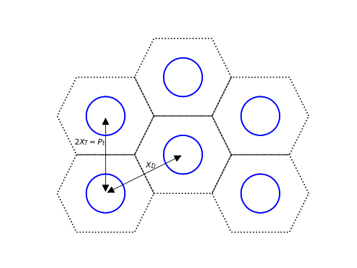
The effective radius ratio is given by
And the \(m\) factor is given by
\(c_s/c_p\) is the correction for heat/mass transfer for a wetted surface. If the fins are dry, this parameter is set to unity, which yields the standard definition for the parameter \(m\) for a fin
Fin efficiency based on analysis by Hong & Webb [2] and Perrotin & CLODIC [1] for wet and dry fins with staggered fins
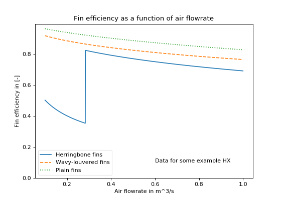
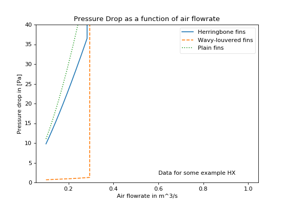
Plots

Overall efficiency
Once the finned surface efficiency (\(\eta_f\)) is known, the overall surface efficiency is given by
References
| [1] | Thomas Perrotin, Denis Clodic, 2003, “Fin Efficiency Calculation in Enhanced Fin-and-Tube Heat Exchangers in Dry Conditions”, International Congress of Refrigeration |
| [2] | Kwang Taek Hong and Ralph L. Webb, 1996, “Calculation of Fin Efficiency for Wet and Dry Fins” HVAC&R Research,v. 2 Link to File |
| [3] | Chi-Chuan Wang and Yu-Min Tsai and Ding-Chong Lu, 1998, “Comprehensive Study of Convex-Louver and Wavy Fin-and-Tube Heat Exchangers”, Journal of Thermophysics and Heat Transfer |
| [4] | Schmidt T.E. 1945-46. La Production Calorifique des Surfaces Munies D’ailettes. Bulletin De L’Institut International Du Froid Annexe G-5. |
Nomenclature
| Variable | Description |
|---|---|
| \(A_{a,total}\) | Total air-side area (fins+tubes) [m2] |
| \(A_f\) | Air-side area of fins [m2] |
| \(A_{1fin}\) | Air-side area of 1 fin [m2] |
| \(A_c\) | Cross-sectional area of duct not filled with fins and tubes [m2] |
| \(A_{r,total}\) | Surface area on the refrigerant (or fluid) side [m2] |
| \(A_{duct}\) | Duct cross-sectional area [m2] |
| \(A_{tube}\) | Cross-sectional area of the tubes [m2] |
| \(c_{p,a}\) | Air specific heat [J/kgha/K] |
| \(D_i\) | Interior diameter of tubes [m] |
| \(G_c\) | Air mass flux [kg/m2] |
| \(f_{a,total}\) | Air-side friction factor [-] |
| \(FPI\) | Fins per inch [1/in] |
| \(FPM\) | Fins per meter [1/m] |
| \(k_{fin}\) | Fin conductivity [W/m/K] |
| \(H\) | Height [m] |
| \(j\) | Colburn j-factor [-] |
| \(L_{tube}\) | Length of one tube [m] |
| \(L_{tubes,total}\) | Sum total length of all tubes [m] |
| \(\overline{L_{circuit}}\) | Average length of circuit [m] |
| \(m\) | Non-dimensional group in fin efficiency calculation [-] |
| \(\dot m_{ha}\) | Mass flow rate of humid air [kg/s] |
| \(N_{tubes/bank}\) | Number of tubes per bank [-] |
| \(N_{bank}\) | Number of banks of tubes [-] |
| \(N_{circuits}\) | Number of circuits [-] |
| \(N_{fin}\) | Number of fins [-] |
| \(p_f\) | Twice the amplitude of fins corrugation [m] |
| \(p_l\) | Longitudinal bank-bank pitch (in the flow direction)[m] |
| \(p_t\) | Transverse pitch (perpindicular in the flow direction)[m] |
| \(\Delta p_a\) | Air side pressure drop [Pa] |
| \(\mathrm{Pr}\) | Prandtl number [-] |
| \(r\) | Outer radius of tube [m] |
| \(r_f\) | Circular fin radius [m] |
| \(\mathrm{Re}_D\) | Reynolds number based on tube OD [-] |
| \(s\) | Spacing between fins [m] |
| \(\sec \theta\) | Area increase factor [-] |
| \(t\) | Fin thickness [m] |
| \(u_{max}\) | Maximum air velocity [m/s] |
| \(v_{ha}\) | Density of humid air [m^3/kg] |
| \(\dot V_{ha}\) | Volumetric flow rate of humid air [m3/s] |
| \(V_{r,total}\) | Open volume on the refrigerant (or fluid) side [m3] |
| \(W\) | Humidity ratio [-] |
| \(x_f\) | Half-wavelength of fin wave [m] |
| \(X_D\) | Diagonal distance in fin efficiency equation [m] |
| \(X_T\) | Transverse distance in fin efficiency equation [m] |
| \(\alpha_a\) | Air-side mean heat transfer coefficient [W/m2/K ] |
| \(\rho_{ha}\) | Density of air [kg/m3] |
| \(\phi\) | Surface efficiency parameter [-] |
| \(\eta_a\) | Overall finned surface efficiency [-] |
| \(\eta_f\) | Fin efficiency [-] |