Cycle Solver Preconditioner
The basic idea of a preconditioner is to use an extremely simple model in order to obtain good initial values for the solver used for the cycle in ACHP.
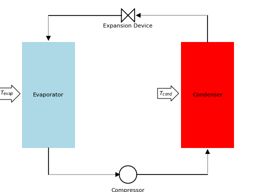
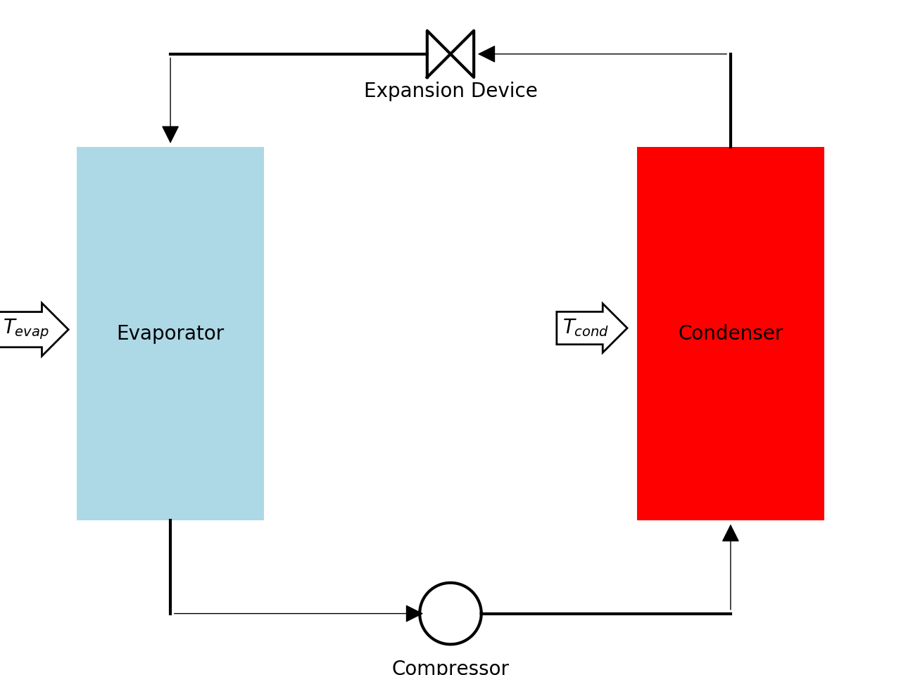
Conventional system
(Source code, png, hires.png, pdf)

The following assumptions are employed in the preconditioner employed for the conventional heat pump and air conditioning models:
- Condenser air stream is the minimum capacitance rate in the condenser, and the limiting outlet state for the air in the condenser is \(T_{cond}\). [This further assumes that there is no subcooled section, but this is ok, because there is also a pinch point at the saturated liquid point, so the basic analysis still works. In the end, the preconditioner is only used to get an approximate solution anyway, so inaccuracy is acceptable, as long as it is reasonable.]
- Effectiveness of all heat exchangers is known, and fixed
- Compressor inlet superheat is fixed and known
- Compressor is adiabatic
- Evaporator is fully wet, fully dry, or a simple weighted mix of the two
- Line sets are not considered
Essentially the preconditioner operates with the same independent variables as ACHP, which are the dew temperatures of the refrigerant in the evaporator and condenser, given by the variables \(T_{evap}\) and \(T_{cond}\) respectively.
Compressor
For a given set of \(T_{evap}\), \(T_{cond}\), and known superheat \(\Delta T_{sh}\), the inlet state and outlet pressure for the compressor is known. Therefore, the compressor map can be used to predict the refrigerant mass flow rate as well as the compressor power. This yields the values
Condenser
The heat transfer rate in the condenser can therefore be given by the value
The condenser heat transfer rate based on the imposed subcooling can also be given by
Theoretically these two heat transfer rate terms should match, and consistency is imposed by the numerical solver that is employed.
Evaporator
As usual, the evaporator is the most complicated component due to the possibility of the evaporator coil being fully wet, fully dry, or partially wet and partially dry. As in the full evaporator model, the evaporator is first considered to be fully dry, yielding the heat transfer rate of
Then using the dry evaporator heat transfer analysis it is possible to determine the surface temperature. The \(\mathrm{UA}\) values can be obtained from
The outlet temperature of the air can be given from
which yields the air inlet surface temperature of
and the air outlet surface temperature of
If both \(T_{s,a,o}\) and \(T_{s,a,i}\) are above the dewpoint temperature of the entering air (\(T_{dp}\)), the rate of heat transfer in the evaporator is equal to the dry-analysis heat transfer rate. If both \(T_{s,a,o}\) and \(T_{s,a,i}\) are below the dewpoint of the entering air, the coil is entirely wet, for which the heat transfer rate can be obtained from
where \(h_{a,s,evap}\) is the saturated air enthalpy at \(T_{evap}\) and \(h_{a,i}\) is the enthalpy of the inlet air to the evaporator.
If the dewpoint of the inlet air is somewhere between \(T_{s,a,o}\) and \(T_{s,a,i}\), the heat transfer rate in the evaporator is given by a simple weighting. This yields the following solution for the evaporator:
Solution Method
The residuals to driven to zero are therefore an overall energy balance over the system, as well as matching \(\dot Q_{cond}\) and \(\dot Q_{cond,\Delta h}\). So the residual vector as a function of \(T_{evap}\) and \(T_{cond}\) can be expressed as
and a two-dimensional solver can be used to drive the norm of \(\vec{\Delta}\) to sufficiently close to zero by altering \(T_{evap}\) and \(T_{cond}\).
Heating Mode
In heating mode, the system schematic remains exactly the same, and the same analysis is used, but the physical geometry of the evaporator and condenser are swapped.
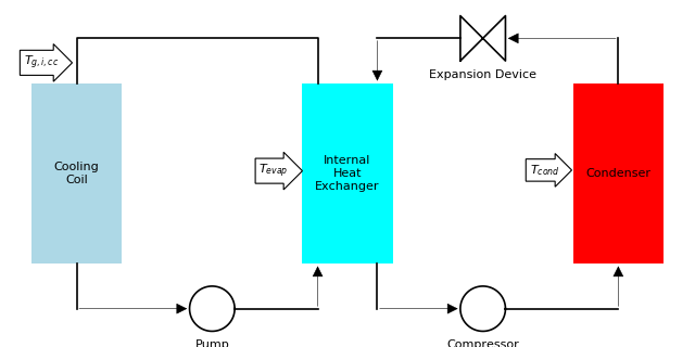
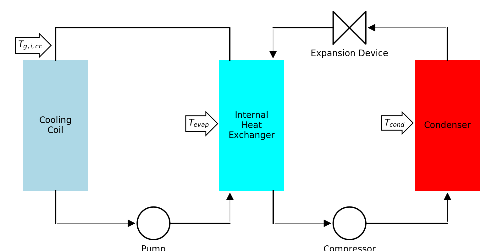
Secondary Loop Systems
(Source code, png, hires.png, pdf)

The same basic structure is employed for the preconditioner for the secondary loop systems, except that one more variable must be determined by the preconditioner. The preconditioner for the secondary loop system is used to determine the saturation temperatures \(T_{evap}\) and \(T_{cond}\), as well as the cooling coil inlet temperature \(T_{g,i,cc}\).
The same exact analysis as for the DX preconditioner is employed for the compressor and condenser, and a very similar analysis is used for the cooling coil. The cooling coil analysis mirrors that of the evaporator, as described here.
Cooling Coil
The cooling coil is first considered to be fully dry, yielding the heat transfer rate of
Then using the dry cooling coil heat transfer analysis it is possible to determine the surface temperature. The \(\mathrm{UA}\) values can be obtained from
The outlet temperature of the air can be given from
which yields the air inlet surface temperature of
and the air outlet surface temperature of
If both \(T_{s,a,o}\) and \(T_{s,a,i}\) are above the dewpoint temperature of the entering air (\(T_{dp}\)), the rate of heat transfer in the evaporator is equal to the dry-analysis heat transfer rate. If both \(T_{s,a,o}\) and \(T_{s,a,i}\) are below the dewpoint of the entering air, the coil is entirely wet, for which the heat transfer rate can be obtained from
where \(h_{a,s,cc}\) is the saturated air enthalpy at \(T_{g,i}\) and \(h_{a,i}\) is the enthalpy of the inlet air to the cooling coil.
If the dewpoint of the inlet air is somewhere between \(T_{s,a,o}\) and \(T_{s,a,i}\), the heat transfer rate in the cooling coil is given by a simple weighting. This yields the following solution for the cooling coil:
Internal Heat Exchanger
Once the cooling coil code has been run, the glycol outlet temperature of the cooling coil can be obtained from
The heat transfer rate in the internal heat exchanger is then given by
because the glycol is the limiting capacitance rate in the two-phase portion of the IHX.
Solution Method
The residuals to driven to zero are therefore an overall energy balance over the refrigerant loop, matching \(\dot Q_{cond}\) and \(\dot Q_{cond,\Delta h}\), and an energy balance over the secondary loop. So the residual vector as a function of \(T_{evap}\), \(T_{cond}\), and \(T_{g,i,cc}\) can be expressed as
and a three-dimensional solver can be used to drive the norm of \(\vec{\Delta}\) to sufficiently close to zero by altering \(T_{evap}\), \(T_{cond}\), and \(T_{g,i,cc}\).
The code for the preconditioners can be found in Preconditioners.py
Nomenclature
| Variable | Description |
|---|---|
| \(\alpha_g\) | Mean glycol heat transfer coefficient [W/\(\mathrm{m}^2\)/K] |
| \(\alpha_r\) | Mean refrigerant heat transfer coefficient [W/\(\mathrm{m}^2\)/K] |
| \(\alpha_a\) | Mean air heat transfer coefficient [W/\(\mathrm{m}^2\)/K] |
| \(\vec{\Delta}\) | Residual vector [W] |
| \(\eta_a\) | Overall air-side surface efficiency [-] |
| \(\varepsilon_{HX}\) | Effectiveness of heat exchangers [-] |
| \(\rho_{da}\) | Density of humid air [kgda/m3] |
| \(A_{a,total}\) | Total air-side surface area of evaporator (fins+tubes) [\(\mathrm{m}^2\)] |
| \(A_{r,total}\) | Total refrigerant-side surface area of evaporator [\(\mathrm{m}^2\)] |
| \(c_{p,a}\) | Specific heat of humid air [J/kgda/K] |
| \(h_{a,s,cc}\) | Enthalpy of air saturated at \(T_{g,i,cc}\) [J/kgda] |
| \(h_{a,s,sat}\) | Enthalpy of air saturated at \(T_{evap}\) [J/kgda] |
| \(h_{a,i}\) | Enthalpy of air inlet to evaporator [J/kgda] |
| \(h_{r,o,comp}\) | Compressor outlet enthalpy [J/kg] |
| \(T_{a,i,cond}\) | Condenser air inlet dry-bulb temperature [K] |
| \(T_{a,i,cc}\) | Cooling coil air inlet dry-bulb temperature [K] |
| \(T_{a,o,cc}\) | Cooling coil outlet dry-bulb temperature [K] |
| \(T_{a,i,evap}\) | Evaporator air inlet dry-bulb temperature [K] |
| \(T_{a,o,evap}\) | Evaporator air outlet dry-bulb temperature [K] |
| \(T_{g,i,cc}\) | Cooling coil glycol inlet temperature [K] |
| \(T_{g,o,cc}\) | Cooling coil glycol outlet temperature [K] |
| \(T_{dp}\) | Dewpoint temperature of humid air [K] |
| \(T_{evap}\) | Evaporator dew temperature [K] |
| \(T_{cond}\) | Condenser dew temperature [K] |
| \(T_{s,a,i}\) | Surface temperature of air at air inlet [K] |
| \(T_{s,a,o}\) | Surface temperature of air at air outlet [K] |
| \(\Delta T_{sh}\) | Compressor suction superheat [K] |
| \(\Delta T_{sc}\) | Condenser outlet subcooling [K] |
| \(p_{cond}\) | Condenser pressure [Pa (abs)] |
| \(\dot m_g\) | Mass flow rate of glycol [kg/s] |
| \(\dot m_r\) | Mass flow rate of refrigerant [kg/s] |
| \(\dot m_{a,total}\) | Mass flow rate of dry air through evaporator [kgda/s] |
| \(\dot Q_{evap}\) | Evaporator heat transfer rate [W] |
| \(\dot Q_{evap,dry}\) | Evaporator fully-dry heat transfer rate [W] |
| \(\dot Q_{evap,wet}\) | Evaporator fully-wet heat transfer rate [W] |
| \(\dot Q_{cc}\) | Cooling Coil heat transfer rate [W] |
| \(\dot Q_{cc,dry}\) | Cooling Coil fully-dry heat transfer rate [W] |
| \(\dot Q_{cc,wet}\) | Cooling coil fully-wet heat transfer rate [W] |
| \(\dot Q_{cond}\) | Condenser heat transfer rate [W] |
| \(\dot Q_{cond,\Delta h}\) | Condenser heat transfer rate from change in enthalpy [W] |
| \(\dot Q_{IHX}\) | Internal Heat Exchanger heat transfer rate [W] |
| \(\mathrm{UA}_a\) | Air-side \(\mathrm{UA}\) value [W/K] |
| \(\mathrm{UA}_g\) | Glycol-side \(\mathrm{UA}\) value [W/K] |
| \(\mathrm{UA}_r\) | Refrigerant-side \(\mathrm{UA}\) value [W/K] |
| \(\dot V_{ha,cond}\) | Volumetric flow rate of humid air in condenser [m3/s ] |
| \(\dot V_{ha,evap}\) | Volumetric flow rate of humid air in evaporator [m3/s ] |
| \(\dot V_{ha,cc}\) | Volumetric flow rate of humid air in cooling coil [m3/s ] |
| \(\dot W_{comp}\) | Electrical power of compressor [W] |